Charpy Testing.
Preventing Catastrophic Metal Failures.
THE EVOLUTION OF THE
CHARPY
V-NOTCH TEST
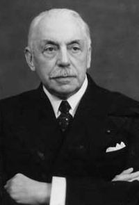
The impact-pendulum test method and associated equipment in nearly its current form was first developed more than a century ago. And while the basic concept behind this testing method is generally credited to two different engineers, S. B. Russell (1898) and G. Charpy in (1901); the test is now known by only the latter's name. The reason for this is due in large part to Georges Augustin Albert Charpy's technical contributions in the first half of the 20th century. These efforts included writing testing procedures in the use of a pendulum to apply an impact force to a specimen and measure the amount of energy absorbed during its fracture.
 Preventing Catastrophic Metal Failures
As a young engineer in France, Charpy's own interest in measuring the impact resistance of steel was fueled by his desire to uncover the issues behind premature failures in marine artillery and other armaments, his area of special expertise, as well as steam boiler and steam engine mishaps. The early development of material testing methods, like Charpy's, was also driven by the rapid expansion of the global railway network between about 1830 and 1900, and the large number of failures of axles and rails. Many of these failures caused catastrophic accidents without any warning because they were brittle failures and the fractures were not preceded by any discernible visible deformation to serve as a warning of incipient fracture. Preventing these incidents required characterization of brittle and ductile behavior of materials, as well as the clarification of the ductile-brittle transition behavior of metals (DBTT).
Better Understanding the ductile to brittle
transition behavior of metals.
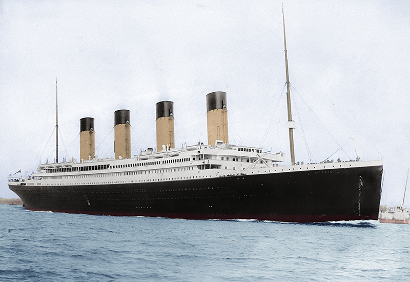
The RMS Titanic departing Southampton, England, for its maiden voyage to New York on April 10, 1912. After stops in France and Ireland, the ship would hit an iceberg just four days later, 375 miles south of Newfoundland, eventually breaking apart and sinking within hours of the initial impact. It is believed that Charpy's original tests were conducted at room temperature or above, instead of the sub-zero temperatures the ship's hull was subjected to in the frigid waters of the North Atlantic.
In the early 20th century, the role of ductile to brittle transition was not well understood and it is believed that Charpy's original tests were conducted at room temperature or above. If it were, the steel plates manufactured in 1910 for the RMS Titanic could have been tested at sub-zero temperatures. This may have revealed the brittle behavior caused when the Titanic's hull was subjected to a temperature of -2ºC in the North Atlantic, before encountering an enormous iceberg. This issue came to the forefront again during WWII when the Liberty ships' steel welds fractured at extreme temperatures; causing catastrophic crack propagation. In some cases, this even occurred while the ships were in port.
The situation became even more serious when it was discovered that machine components could also fail at stress levels well below the critical fracture stress. All that was necessary for this type of failure to occur was the presence of cyclic load fluctuations, either random or periodic. It was observed (although the reason was not understood until later) that a fracture would originate and initiate at certain locations and slowly, then more rapidly, propagate into the material and finally rupture the component, most often in a brittle fashion. Thus, a new type of failure, fatigue, was identified.
FATIGUE FAILURE and The Charpy V-notch Configuration
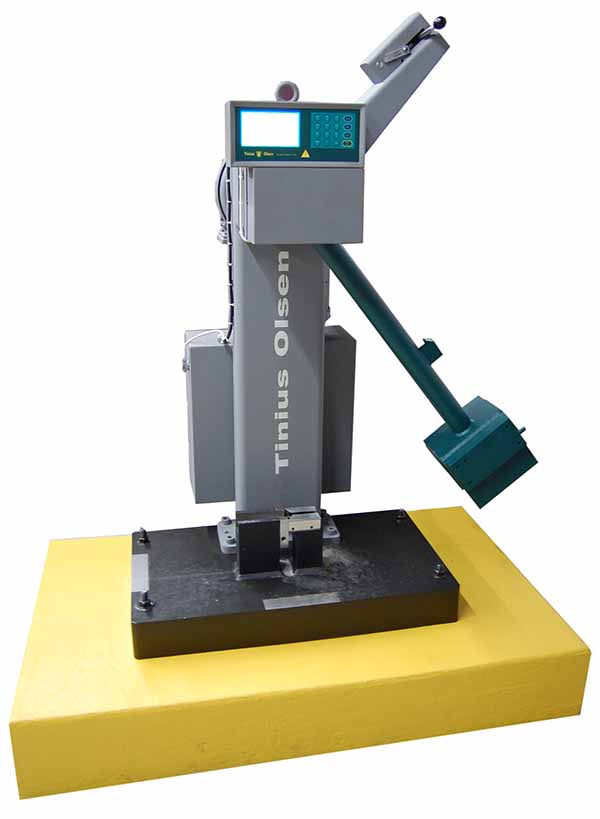
Once it was understood that fatigue damage propagated by the growth of a sharp crack through a component, a variety of notch configurations were added to specimens to evaluate how their performance was degraded by such damage. With the Charpy V-notch Test (CVN) specimens are usually cut from the actual part or weldments using an abrasive cut off saw or a band saw with low heat input. Base metal specimen is 55 mm (about 2.25" inches) in length, 10 mm thick and 10 mm wide. Centerline of the Charpy specimen is notched according to standard with a special broach to create the required V-Notch with the appropriate dimensions and surface finish. Threaded fasteners and pipe have special considerations. The specimens are tested either at room temperature or at a series of specified temperatures, such as -20ºC, -10ºC, 0ºC, +10ºC, +20ºC.
Today, The Charpy Impact Test is used for large, outdoor engineering structures, including as bridges, ships, hi-rise buildings and towers; as well as pressure vessels, valves and fittings used in the oil and gas industry, related piping, pipelines, off-highway mining, farming vehicles, industrial equipment, to validate welds, and more.
Why choose ATRONA Test Labs for your next Charpy Impact Test?
As an independent, accredited mechanical test lab, Charpy Impact Testing is conducted at ATRONA on a daily basis per ASTM A370/E23. ATRONA has two high capacity pendulum impact testers and employs state of the art sample preparation and testing methods. Part size does not matter. Hardness of the part does not matter either. Our capabilities include 16 cutting machines ranging in size from high speed diamond saws to a very large double column band saw that can cut 40" by 40" part. All saws are capable of cutting hard materials with carbide blades. We can also heat or cool the Charpy samples prior to testing or test at room temperature. We offer competitive prices and fast turnaround times.
Credit: This article was written using information from various sources, including the National Institute of Standards and Technology (NIST). Photo of Titanic by Francis Godolphin Osbourne Stuart.